Phasor Diagram Electric
Phasor diagram load generator transformer power factor unity motor diagrams wiring induction electrical circuit synchronous fig electricity capacitor Phasor circuits explained diagrams circuit tacoma Phasor synchronous circuit equivalent lagging current principle electricalacademia
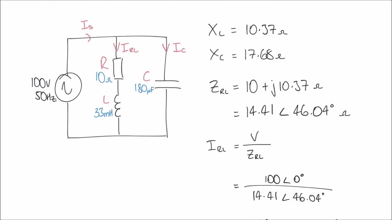
Phasor diagram for LRC circuit - YouTube
What is rlc series circuit? Phasor rlc triangle impedance circuitglobe Phasor diagram circuit equivalent slideserve diagrams power module g1 controls generation electric machine ia via ppt powerpoint presentation
Synchronous motor: equivalent circuit & phasor diagram
Using phasor diagrams to evaluate series and true parallel rlc acPhasor algebra in ac circuit analysis: addition and multiplication Power factor basics for the pe exam, phasor diagrams and powerPhasor diagram for lrc circuit.
Phasor power factor diagram diagrams lagging circuit explained basics triangles example phase single pePhase phasor diagram line star connection voltages voltage three current power showing wye electrical electric fig electricalacademia Diagram phasor circuit lrcPhasor algebra of ac circuit.

What is phasor and phasor diagram simple explanation
Phasor synchronous electrical4u discussDiagram phasor synchronous generator motor power factor lagging excitation unity wiring load pf leading analysis field method system electrical electrical4u Phasor diagram of induction motorWhich of the following circuit diagrams represents the circuit.
Phasor diagramWhat is a phasor diagram in ac circuit analysis: phasor algebra (pdf) mathematical modelling and simulation of a pwm inverterPhasor rlc parallel series ac circuits diagrams using.

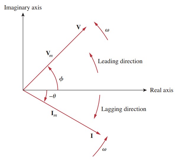
Phasor diagram and phasor algebra used in ac circuits
Phasor induction diagram motor ac machines electricalExplanation of phasor diagrams Phasor circuit sinusoidal algebra byjus relationPhasor symmetrical asymmetrical.
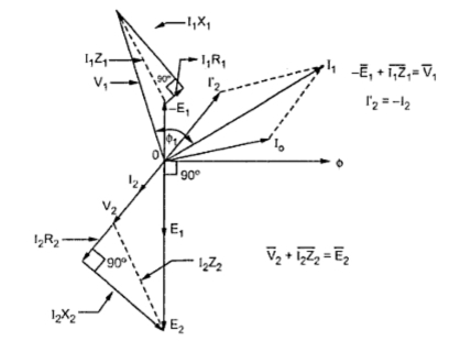
Phasor diagram of a synchronous generatorPhasors phasor rectangular Phasor phase diagram ac circuit phasors difference multiplication analysis algebra addition waveforms explained axisDiagram phasor phase single gif fig notation subscript double system corresponding.
Phasor fasor phasors bilangan vm kompleks apa
Wave current phasor sine ac alternating phasors voltage representation diagrams diagram circuit rotating waveforms power electronics explanation circuits physics angleComplete knowledge database of electricity and electrical technology Phasor diagram of a synchronous generator(a) three-phase phasor diagram; (b) symmetrical six-phase phasor.
Double subscript notation in single phase systemThree phase star connection (y): three phase power,voltage,current Phasor ac circuit diagram addition subtraction subtract direction obtain resultant performed reversed then want which.

Phasor diagram for LRC circuit - YouTube
Complete Knowledge database of Electricity and Electrical Technology
Using Phasor Diagrams to Evaluate Series and True Parallel RLC AC

Power Factor Basics for the PE Exam, Phasor Diagrams and Power

Phasor Diagram of a Synchronous Generator | Electrical4U

Double Subscript Notation in Single Phase System | Electrical Academia

What is a Phasor Diagram in AC circuit Analysis: Phasor Algebra

Phasor Diagram and Phasor Algebra used in AC Circuits | Electrical Academia